
Magnetocaloric cooling is often explained with one simple idea: some magnetic materials heat up in a magnetic field and cool down when the field is removed. That statement is true, but it only describes the material effect.
A working refrigerator, air conditioner, or heat pump needs more than a responsive material. It needs a full system that can move heat from a cold region to a warmer region, much like conventional systems do with a refrigerant — the substance used to carry heat in a cooling cycle. In magnetocaloric cooling, part of that role is shifted from a circulating gas to a magnetic material that heats and cools when the magnetic field changes.
This article looks beyond the basic material effect. It explains how the magnetic material, magnetic-field source, fluid loop, regenerator, heat exchangers, and system design choices work together to turn magnetic heating and cooling into a practical thermal machine.
1. From Magnetic Effect to Cooling System
The physical principle behind magnetic cooling is the magnetocaloric effect, or MCE. In certain magnetic materials, magnetic moments become more ordered when a magnetic field is applied, causing the material to warm. When the field is removed, the moments become more disordered and the material cools. Researchers describe this response using quantities such as magnetic entropy change, or ΔSm, and adiabatic temperature change, or ΔTad [1,2].
Those material-level quantities are important, but they do not describe the whole machine. A practical device must remove heat from the material after magnetization and absorb heat after demagnetization. It must also repeat this process many times while controlling heat transfer, fluid flow, magnetic-field exposure, and mechanical losses.
In other words, magnetocaloric refrigeration is not only about whether a material heats and cools. It is about whether a system can use that response to move heat reliably and efficiently.
2. What Is Inside the Machine?
A practical magnetocaloric cooling system is built from several connected parts.
One key part is the magnetic-field source. This is often a permanent magnet assembly: a set of magnets arranged to create the magnetic field needed by the system. Its role is to expose the magnetocaloric material to a magnetic field and then remove or reduce that field during the cycle. Laboratory systems may use electromagnets, but permanent magnets are often attractive because they can provide a magnetic field without continuous electrical input to maintain the field. Depending on the device architecture, mechanical work may still be required to move the magnet assembly, the regenerator, or the flow system [3,4].
The next part is the magnetocaloric material. This is the solid material that heats and cools when the magnetic field changes. It plays a role similar to the refrigerant in a conventional vapor-compression system — the standard cooling cycle where a gas is compressed, condensed, expanded, and evaporated to move heat. The difference is that the magnetocaloric material does not evaporate, condense, or circulate as a gas [1–3].
A central component is the Active Magnetic Regenerator, usually called an AMR. In many room-temperature magnetocaloric systems, the magnetocaloric material is arranged inside the AMR as a bed, stack, plate structure, or porous geometry. A heat-transfer fluid flows through or around this structure [4,5].
The AMR has two roles. It is “active” because the material itself produces the magnetocaloric heating and cooling. It is a “regenerator” because it stores and transfers heat along its length. This helps the system build a temperature difference between the cold and hot sides [4,5].
The system also needs a heat-transfer fluid. This fluid carries heat between the AMR and the heat exchangers. The cold heat exchanger absorbs heat from the space, object, or process being cooled. The hot heat exchanger rejects heat to the surroundings or delivers useful heat in heat-pump operation.
Seen as a whole, the device is not simply “a magnet plus a material.” It is a coordinated thermal system made of a magnetic-field source, magnetocaloric material, AMR structure, fluid loop, pump, piston, or other flow actuator, and hot/cold heat exchangers. Figure 1 illustrates this basic architecture, showing how the AMR bed, magnetic-field source, fluid loop, and heat exchangers are arranged to move heat from the cold side to the hot side.
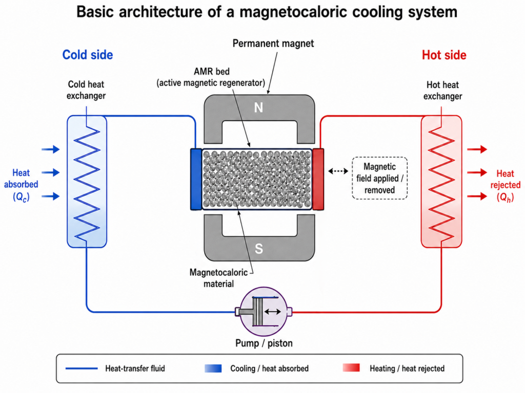
Figure 1. Basic architecture of a magnetocaloric cooling system.
3. How the AMR Helps Build a Useful Temperature Span
A magnetocaloric material may only heat or cool by a limited amount during one magnetic-field change. A real cooling or heating device usually needs a larger temperature difference between the cold side and the hot side. This difference is called the temperature span. For example, a refrigerator must keep its interior cold while rejecting heat to room-temperature air [4–6].
The AMR helps create and maintain this temperature span. During magnetization, the material heats up. Fluid then carries heat toward the hot heat exchanger. During demagnetization, the material cools down. Fluid then helps absorb heat from the cold side.
The important point is not just that the AMR goes through a cycle. The key system challenge is that heat transfer, magnetic-field timing, and fluid motion must work together. If the fluid moves too early, too late, too slowly, or too quickly, the system may lose part of the cooling effect.
This is why AMR design is central to magnetocaloric refrigeration. The geometry, material arrangement, flow rate, cycle frequency, and magnetic-field profile all affect how much useful temperature span the system can maintain [4–6].
4. Pressure Drop: A Hidden System Trade-Off
One practical issue that is easy to overlook is pressure drop. Pressure drop means the pressure loss that occurs as the heat-transfer fluid passes through the AMR bed, channels, valves, and heat exchangers [4–6].
This matters because moving fluid through the system requires work. If the AMR has very small pores or narrow channels, the fluid may contact more material surface. That can improve heat transfer. At the same time, smaller flow paths can increase resistance. The pump or actuator must then work harder, which can reduce the net system efficiency.
This creates a design trade-off. More contact area between the fluid and the magnetocaloric material can improve heat exchange and support higher cooling capacity. However, narrower flow paths can also increase flow resistance and pressure drop. When pressure drop increases, the pump or actuator must do more work, which can reduce the net COP. A good AMR design therefore needs to balance heat transfer and pressure drop, as illustrated in Figure 2.
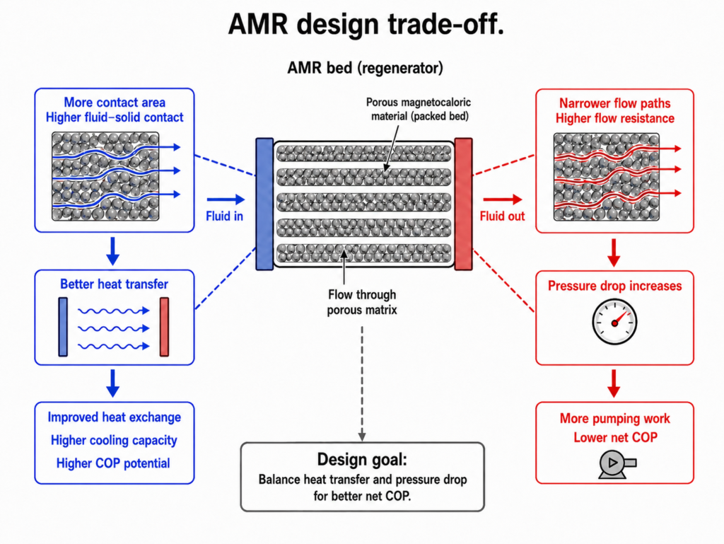
Figure 2. AMR design trade-off.
5. How Efficiency Is Evaluated
The efficiency of a cooling or heating system is commonly described by the Coefficient of Performance, or COP. For cooling, COP is the useful cooling delivered divided by the input work required. For heating, it is the useful heat delivered divided by the input work [7].
In magnetocaloric systems, COP is a system-level result. The material matters, but it is only one part of the picture. Magnetic-field design, AMR geometry, fluid-flow timing, heat-exchanger performance, pressure drop, control strategy, and mechanical or electrical losses can all influence the final COP [4–6].
This distinction is important. A magnetocaloric material may show strong performance in laboratory measurements. That does not automatically mean the final device will be highly efficient. The material response still needs to be converted into useful heat pumping with limited losses.
One relevant loss mechanism is hysteresis. Hysteresis means that a material does not follow exactly the same path during magnetization and demagnetization. In magnetocaloric systems, hysteresis can create energy losses and make the cycle less efficient when repeated many times. Some magnetocaloric materials can show strong heating and cooling responses, but controlling hysteresis is important for efficient cycling [8].
Another relevant property is heat capacity at constant pressure, or Cp. Cp describes how much heat is needed to raise the temperature of a material while pressure remains constant. In magnetocaloric materials, heat capacity is one of the thermodynamic quantities that links entropy change and temperature change, so it affects how a material response translates into heating or cooling [9].
These factors show why magnetocaloric cooling is not only a materials problem. It is also a heat-transfer, fluid-flow, magnetic-design, and controls problem.
6. Why Mn–Fe–P–Si Needs System-Level Evaluation
One material family that has received attention for magnetocaloric applications is Mn–Fe–P–Si, based on manganese, iron, phosphorus, and silicon. Its magnetic transition temperature can be adjusted through composition, which is useful for matching the material to different operating ranges [10].
This transition temperature is called the Curie temperature, or Tc. Near Tc, many magnetocaloric materials show their strongest response. For practical refrigerators, air conditioners, or heat pumps, the material should operate near the temperature range required by the application. A tunable Tc is useful because it allows the material to be matched more closely to different operating conditions [2,10].
Mn–Fe–P–Si is not a complete solution by itself. Like other magnetocaloric materials, it must be evaluated in a full system. Hysteresis, processing control, mechanical stability, corrosion behavior, heat-transfer geometry, and long-term cycling performance all matter. A promising material still needs to work reliably inside an AMR device with acceptable pressure drop, suitable temperature span, and competitive COP [4,8,10].
More broadly, ferroic cooling materials should not be judged only by peak entropy change or peak temperature change. Losses, hysteresis, field requirements, operating range, and system integration also affect whether a material is useful in a real device [11].
7. Environmental Impact: Direct Benefits and Full-Life-Cycle Questions
Magnetocaloric systems may offer environmental advantages because they can use magnetic materials instead of conventional refrigerant gases. This can help avoid direct refrigerant-gas leakage emissions during operation and servicing.
This point connects to Global Warming Potential, or GWP. GWP measures how much heat a greenhouse gas traps in the atmosphere compared with carbon dioxide over a selected time period. Avoiding high-GWP refrigerant leakage is one potential environmental benefit of magnetocaloric cooling technologies [12].
Still, environmental performance should be evaluated across the full life cycle, from material production and manufacturing to electricity use, durability, and end-of-life handling. The strongest case for magnetocaloric cooling will come from combining low direct refrigerant impact with efficient system performance and durable, scalable materials.
Conclusion
Magnetocaloric cooling is often described as “cooling with magnets.” A working device, however, is more than a magnetic effect. It is a complete thermal system that combines magnetic materials, magnetic-field control, fluid flow, regeneration, heat exchange, and system timing.
The central engineering task is to turn a material-level temperature response into useful cooling or heating across a practical temperature span. AMR design, pressure drop, COP, hysteresis, Curie temperature, and heat-transfer performance all influence how well this can be achieved.
In that sense, magnetocaloric cooling is not only a materials story. It is a system-design story. Better materials are important, but the success of magnetic cooling will also depend on how well those materials are integrated into efficient, reliable, and manufacturable devices.
References
[1] Pecharsky, V. K., & Gschneidner, K. A. (1999). Magnetocaloric effect and magnetic refrigeration. Journal of Magnetism and Magnetic Materials, 200(1–3), 44–56. https://doi.org/10.1016/S0304-8853(99)00397-2
[2] Gschneidner, K. A., Pecharsky, V. K., & Tsokol, A. O. (2005). Recent developments in magnetocaloric materials. Reports on Progress in Physics, 68(6), 1479–1539. https://doi.org/10.1088/0034-4885/68/6/R04
[3] Fraunhofer IPM. Magnetocaloric materials & systems. Fraunhofer Institute for Physical Measurement Techniques IPM. https://www.ipm.fraunhofer.de/en/bu/gas-and-process-technology/expertise/caloric-systems/magnetocaloric-systems.html
[4] Trevizoli, P. V., Liu, Y., Teyber, R., Nielsen, K. K., & Engelbrecht, K. (2020). Review on the developments of active magnetic regenerator refrigerators. Renewable and Sustainable Energy Reviews, 133, 110333. https://doi.org/10.1016/j.rser.2020.110333
[5] Russek, S. L., Zimm, C. B., & Boeder, A. M. (2018). The evolution of magnetocaloric heat-pump devices. MRS Bulletin, 43, 280–284. https://doi.org/10.1557/mrs.2018.71
[6] Bjørk, R., & Engelbrecht, K. (2015). The influence of the magnetic field on the performance of an active magnetic regenerator. International Journal of Refrigeration, 54, 146–151. https://doi.org/10.1016/j.ijrefrig.2015.03.001
[7] Moran, M. J., Shapiro, H. N., Boettner, D. D., & Bailey, M. B. (2018). Fundamentals of Engineering Thermodynamics (9th ed.). Wiley.
[8] Gutfleisch, O., Gottschall, T., Fries, M., Benke, D., Radulov, I., Skokov, K. P., Wende, H., Gruner, M., Acet, M., Entel, P., & Farle, M. (2016). Mastering hysteresis in magnetocaloric materials. Philosophical Transactions of the Royal Society A, 374, 20150308. https://doi.org/10.1098/rsta.2015.0308
[9] Pecharsky, V. K., & Gschneidner, K. A. (2001). Thermodynamics of the magnetocaloric effect. Physical Review B, 64, 144406. https://doi.org/10.1103/PhysRevB.64.144406
[10] You, X., et al. (2022). Magnetic phase diagram of the MnxFe2−xP1−ySiy system. Entropy, 24(1), 2. https://doi.org/10.3390/e24010002
[11] Brück, E., Yibole, H., & Zhang, L. (2016). A universal metric for ferroic energy materials. Philosophical Transactions of the Royal Society A, 374, 20150303. https://doi.org/10.1098/rsta.2015.0303
[12] U.S. Environmental Protection Agency. Understanding Global Warming Potentials. https://www.epa.gov/ghgemissions/understanding-global-warming-potentials


